Bridge Design:
Design Brief
Procedure
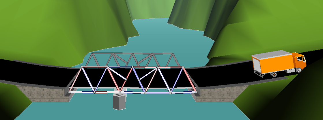
Your team will design and create a bridge utilizing West Point Bridge Designer software. West Point Bridge Designer is a simplified and scaled down computer-aided design tool developed by Colonel Stephen Ressler, Department of Civil and Mechanical Engineering, U.S. Military Academy, West Point, New York. The software will allow you to apply engineering design, material science, and statics to the design of a truss bridge carrying a two-lane highway that spans a riverbed.
Design Constraints
o If the elevation of the bridge deck is below 24 meters, excavation of the riverbanks will be required to achieve the correct highway elevation.
o To provide clearance for overhead power lines, the highest point on the bridge may not exceed an elevation 32.5 meters above the high water level (8.5 meters above the top of the riverbanks).
o The bridge substructure may consist of either standard abutments (simple supports) or arch abutments (arch supports). If necessary, the bridge may also use one intermediate pier, located near the center of the valley. If necessary, the bridge may also use cable anchorages, located 8 meters behind one or both abutments.
o Each main truss can have no more than 50 joints and no more than 120 members.
o The bridge will have a flat, reinforced concrete deck. Two types of concrete are available:
o Cross Sections—The members of the truss can be either solid bars or hollow tubes. Both types of cross sections are square.
o Member Size—Both cross sections are available in a variety of standard sizes.
o Weight of a 5-cm thick asphalt wearing surface, which might be applied at some time in the future.
o Weight of the steel floor beams and supplemental bracing members (assumed to be 12.0 kN applied at each deck-level joint).
o Weight of the main trusses.
o Either of two possible truck loadings:
1. Weight of one standard H25 truck loading per lane, including appropriate allowance for the dynamic effects of the moving load. Since the bridge carries two lanes of traffic, each main truss must safely carry one H25 vehicle, placed anywhere along the length of the deck.
2. Weight of a single 480 kN Permit Loading, including appropriate allowance for the dynamic effects of the moving load. Since the Permit Loading is assumed to be centered laterally, each main truss must safely carry one-half of the total vehicle weight, placed anywhere along the length of the deck.
o Load combinations
o Tensile strength of members
o Compressive strength of members
Cost Calculations
The cost of the design will be calculated using the following cost factors:
o Carbon steel tubes—$6.30 per kilogram
o High-strength steel bars—$4.62 per kilogram
o High-strength steel tubes—$7.03 per kilogram
o Quenched and tempered steel bars—$5.70 per kilogram
o Quenched and tempered steel tubes—$7.95 per kilogram
o Connection cost—$300.00 per joint
o Product cost—$1000.00 per product
o Reinforced concrete deck (high strength)—$5,500 per 4-meter panel
o Excavation—$1.00 per cubic meter (see the Site Design Wizard for excavation volume)
o Supports (abutments and pier)—cost varies (see the Site Design Wizard for specific values)
o Cable Anchorages—$6,000 per anchorage
Your team will design and create a bridge utilizing West Point Bridge Designer software. West Point Bridge Designer is a simplified and scaled down computer-aided design tool developed by Colonel Stephen Ressler, Department of Civil and Mechanical Engineering, U.S. Military Academy, West Point, New York. The software will allow you to apply engineering design, material science, and statics to the design of a truss bridge carrying a two-lane highway that spans a riverbed.
Design Constraints
- Minimization of Cost (Design success will be evaluated based upon structural stability and overall cost—decrease the cost and improve the design.)
- Bridge Configuration
o If the elevation of the bridge deck is below 24 meters, excavation of the riverbanks will be required to achieve the correct highway elevation.
o To provide clearance for overhead power lines, the highest point on the bridge may not exceed an elevation 32.5 meters above the high water level (8.5 meters above the top of the riverbanks).
o The bridge substructure may consist of either standard abutments (simple supports) or arch abutments (arch supports). If necessary, the bridge may also use one intermediate pier, located near the center of the valley. If necessary, the bridge may also use cable anchorages, located 8 meters behind one or both abutments.
o Each main truss can have no more than 50 joints and no more than 120 members.
o The bridge will have a flat, reinforced concrete deck. Two types of concrete are available:
- Medium-strength concrete requires a deck thickness of 23 centimeters (0.23 meter).
- High-strength concrete requires a deck thickness of 15 centimeters (0.15 meter).
- In either case, the deck will be supported by transverse floor beams spaced at 4-meter intervals. To accommodate these floor beams, your structural model must have a row of joints spaced 4 meters apart at the level of the deck. These joints are created automatically within West Point Bridge Designer.
- Member Properties
o Cross Sections—The members of the truss can be either solid bars or hollow tubes. Both types of cross sections are square.
o Member Size—Both cross sections are available in a variety of standard sizes.
- The bridge must be capable of safely carrying the following loads:
o Weight of a 5-cm thick asphalt wearing surface, which might be applied at some time in the future.
o Weight of the steel floor beams and supplemental bracing members (assumed to be 12.0 kN applied at each deck-level joint).
o Weight of the main trusses.
o Either of two possible truck loadings:
1. Weight of one standard H25 truck loading per lane, including appropriate allowance for the dynamic effects of the moving load. Since the bridge carries two lanes of traffic, each main truss must safely carry one H25 vehicle, placed anywhere along the length of the deck.
2. Weight of a single 480 kN Permit Loading, including appropriate allowance for the dynamic effects of the moving load. Since the Permit Loading is assumed to be centered laterally, each main truss must safely carry one-half of the total vehicle weight, placed anywhere along the length of the deck.
- The bridge will comply with the structural safety provisions of the 1994 LRFD AASHTO Bridge Design Specification (Load and Resistance Factor Design), to include:
o Load combinations
o Tensile strength of members
o Compressive strength of members
Cost Calculations
The cost of the design will be calculated using the following cost factors:
- Material Cost:
o Carbon steel tubes—$6.30 per kilogram
o High-strength steel bars—$4.62 per kilogram
o High-strength steel tubes—$7.03 per kilogram
o Quenched and tempered steel bars—$5.70 per kilogram
o Quenched and tempered steel tubes—$7.95 per kilogram
o Connection cost—$300.00 per joint
o Product cost—$1000.00 per product
- Site Cost:
o Reinforced concrete deck (high strength)—$5,500 per 4-meter panel
o Excavation—$1.00 per cubic meter (see the Site Design Wizard for excavation volume)
o Supports (abutments and pier)—cost varies (see the Site Design Wizard for specific values)
o Cable Anchorages—$6,000 per anchorage
Research Summary
Over, under, or straight through the middle? It's a simple-sounding question, but it's challenged every great engineer since ancient times. We want the bridges we cross every day to be safe and level, but Earth's characteristics make that kind of construction an amazing challenge. To solve all of the unanswerable questions a couple of very smart architects came up with the truss system, which is composed of triangles. Compression and Tension are the reason we are able to trust bridges not to fall when we cross them. Compression is when the bridge gets squished and tension is when the bridge gets stretched. These are the opposite of each other. When it comes to compression, a force pushing down on the bridge (for example 50 lbs.), has to have a force pushing up (also 50 lbs.). The same thing for tension. When it’s being stretched one way, it has to also be stretched the same way on the opposite side. This is how bridges work and don’t collapse when we drive across them.
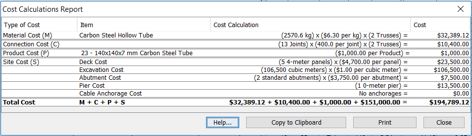
Cost Summary
- Deck Elevation Cost (0 meters) - $138,500
- Pier Cost( 0 meters) - $87,700
- Cable Anchorages(None) - $63,200
- Carbon Steel (Hollow Tube)- $294.00
- Total Cost- $194,789.12
Brainstorming Sketches
|
To the left, this was one of the first designs I tried. I did this just to see what was the cheapest I could get a bridge. This didn't work for obvious reasons, such as there are no truss systems what so ever.
This bridge, was one of the more expensive ones. It used arch abutments and had tensions throughout the whole design, which is why I decided not to use this. As I tried to fix the problems the cost continued to increase.
This standard bridge uses simple trusses but was still very expensive even though it is made of hollow tube members. When I tested this bridge the entire left side collapsed because it had too much tension.
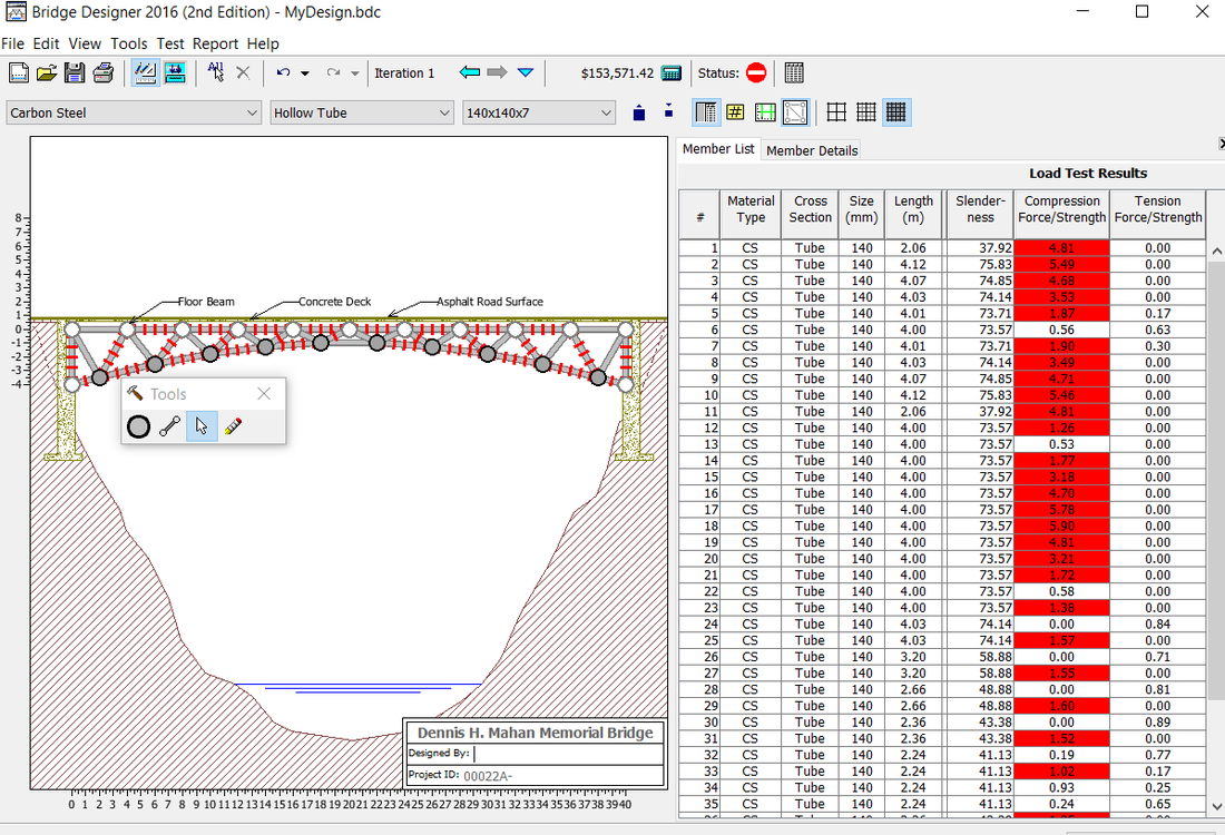
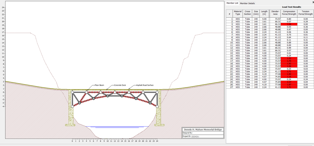
Here is another bridge with an arch. I haven't had any success with the arch abutment yet. This was $153,000 but the design is very poor. No matter what you do with this bridge it wont be safe. There is tension in almost every single member. This bridge is being stretched to its limits.
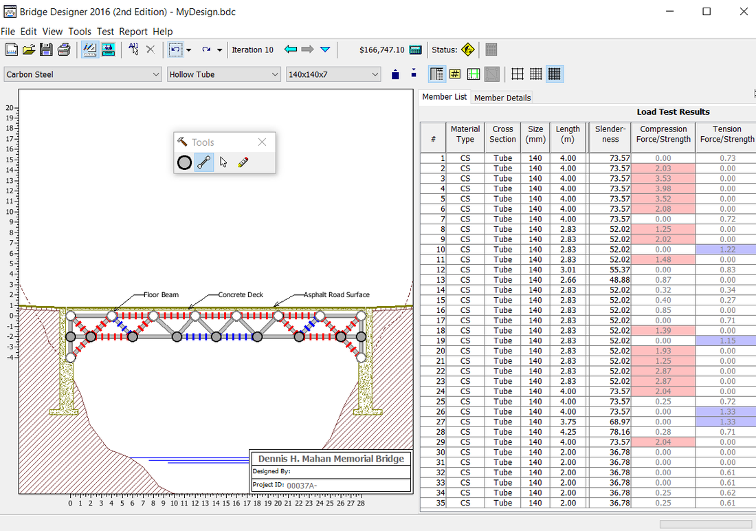
I decided not to use this bridge because it was very expensive. Like other bridges, when I tried to fix it the cost just kept growing. There was more tension than compression. These two factors have to work together but that couldn't happen with this design
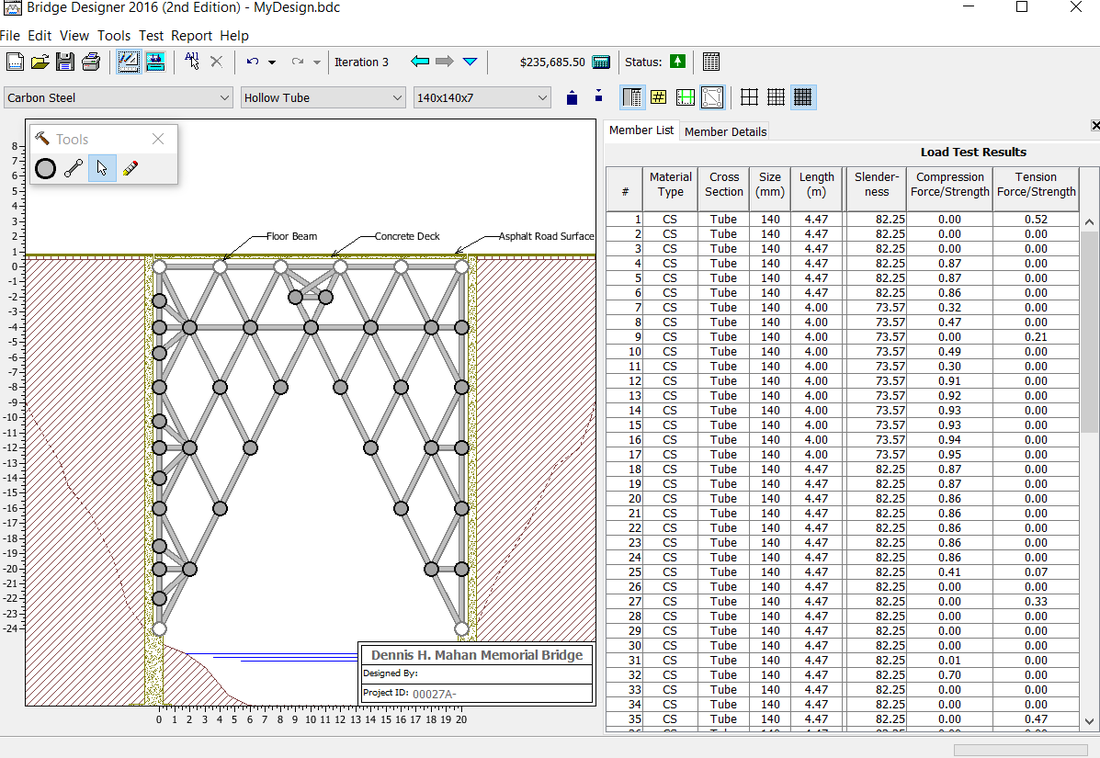
The reason you can't see any blue or red on this bridge was because it actually worked. It was very shady and the last bridge I would want to cross. It was very expensive ($235,685.50) but also the only bridge like this.
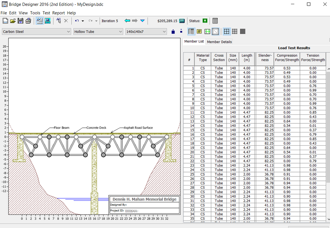
This bridge is the first shown that uses a pier. It made it more expensive but it didn't really matter in the long run. This bridge also works. Even though it is not shown there is some tension and compression. It costs $205,289.15. I could’ve used this bridge but I decided not to because it could be cheaper.
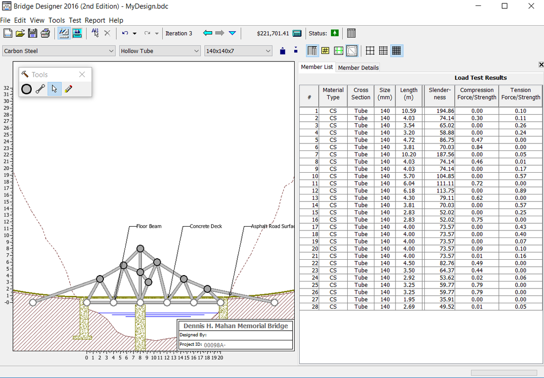
This design uses cable anchors to hold it up. This is yet another bridge that worked. It wasn't the most expensive but it was still pricey. It cost $221,701.41. The cost was the reason I decided not to use this bridge.
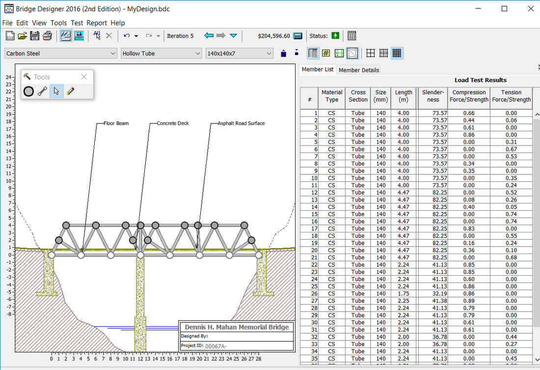
Here is another simple bridge that worked for $204,506.60.
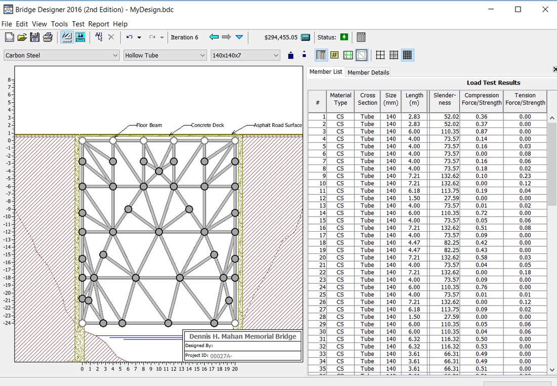
This bridge was the most unrealistic and most expensive costing $294,255.05. These were the main reasons I decided to not use it.
|
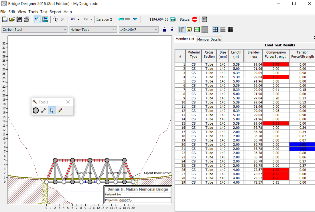
Final Bridge
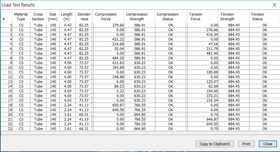
Load Test Report
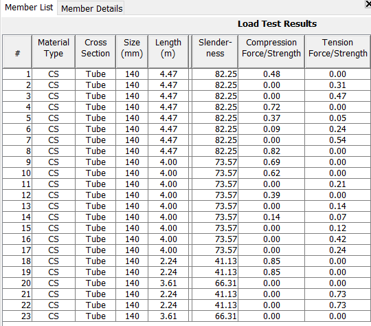
Member Properties
Cost Calculation Report
Justification
I chose to use the hollow tube members and joints because they were a lot cheaper. Also, they weigh less. My final bridge uses a standard truss configuration because it is simple, and would be easiest to build in real life. When I tested that truss configuration and saw where the problem areas were, I added members and joints to solve the problem.
Resources
- Lamb, R., & Morrissey, M. (2000, April 01). How Bridges Work. Retrieved March 20, 2017, from http://science.howstuffworks.com/engineering/civil/bridge2.htm
- History of a Truss Bridge. (n.d.). Retrieved March 20, 2017, from https://www.tn.gov/tdot/article/bridges-historybridges
- How bridges work. (2016, March 26). Retrieved March 20, 2017, from http://www.explainthatstuff.com/bridges.html
Conclusion
1.) Q- How does the type and direction of stress applied affect the selection of the material type and the cross-sectional area?
A- For members that undergo tension you would want materials that are more ductile and capable of stretching so that they wouldn't simply snap under the force. However if it is under compression you might want to use a material that is strongest and resists deformation the most. Also by changing the cross sectional area you can strengthen the material to perform better in tension and compression.
2.) Q- How can the forces of tension and compression work together to make a stronger bridge?
A- By having members that are affected by tension and compression the forces of the load are spread out so that all the force isn't focused on one point. If the members weren't under any force at all the bridge would fail. The tension and compression forces act against each and balance out the forces acting on the bridge so that the joints wont fail.
